Peter,
You are on to something…
You are correct - the TAS5806MD datasheet states that the device is capable of operating at an analog input voltage as low as 4.5v.
The challenge with the SJ-201 design is other locations where the +12v input gets used…
We are almost lucky: if I read the schematics correctly, the +12v input is also used to power the XL4501E1 buck converter to generate +5v. And to power the cooling fan.
The +5v gets sent out the pin header to power up the Pi, and is also down-converted to +3.3v and +1.0v for logic.
The XL4501E1 datasheet says that it can accept an input voltage as low as +8v.
So, maybe we don’t have to put +12v into the power jack of the Mycroft II. Could it run on +8v?
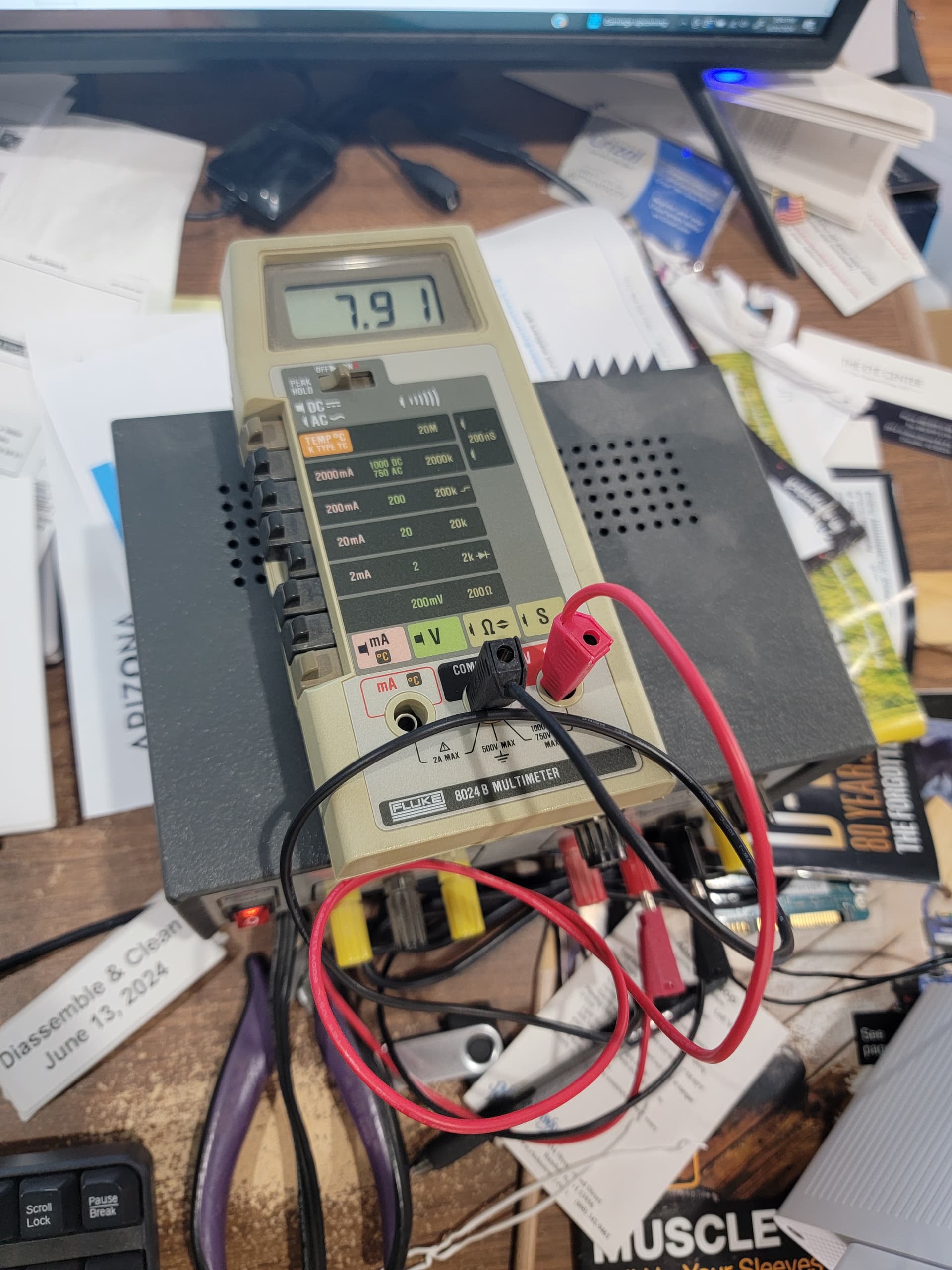
The answer is yes. I was able to boot my Mycroft II (100000 00f7fd 6ce0) using a benchtop power supply (1 amp) set to 8v. I do not have a proper 3 amp power supply capable of a full voltage range, but I did several tests with the following results:
Power Supply & Result
+9v, 1 amp Wall-Wart -Boots Up; functions
+7.5v, 1 amp Wall Wart -No boot, low voltage indication on screen
+8v, 1 amp benchtop power supply -Boots Up; functions
+5v, 3 amp benchtop power supply -No boot; low voltage indication on screen

The key is that operation of the Mycroft at a lower input voltage is going to take the stress off those decoupling caps and likely extend their lifetime.
A side effect of low voltage operation may be compromising the fan operation. From what I understand the Pi 4 has a built-in thermal regulation where it will slow the clock if overheating is imminent. I have not looked at possible fan substitutions to see if lower voltage devices could be substituted.
The takeaway is that lower voltage operation seems feasible. I may be shopping for some lower voltage wall-warts soon.