(Props to Clary for providing the Mycroft II units used in this investigation.)
SHORT VERSION:
*) The “Died Suddenly” behavior of the SJ-201 boards is due to a failure (short) in one or more capacitors C13, C14, C19, and C20.
*) These components are employed as decoupling capacitors on the +12v supply domain powering the TAS5806MD audio amplifier.
*) A review of the SJ-201 BOM (Bill of Materials) shows that the capacitors identified above are rated for only 6.3 volt operation, hence they are prone to failing by shorting. This kills the +12v supply and all power domains derived from +12v.
*) Identification and removal of the offending device(s) will restore the SJ-201 to an operating condition. (See disclaimers at end of this post.)
LONG VERSION:
A short while back I was motivated to review the SJ-201 schematics while diagnosing a fan problem in my Mycroft II.
I was aware of the Mycroft “Died Suddenly” behavior, having experienced it with one of my previously purchased units. I also understood that the problem was attributed to failure of the SJ-201 boards.
When I reviewed the SJ-201 schematic, the power supply configuration appeared to be straightforward – there really wasn’t much to go wrong. Why were the boards failing? In my previous life as a test engineer I acquired some experience with power supply design and testing so I asked Clary if she could provide me a dead SJ-201 to analyze. She was kind enough to provide me a complete Mycroft II with a known defective SJ-201.
SJ-201 Power Supply and Domains Overview (Schematics Review):
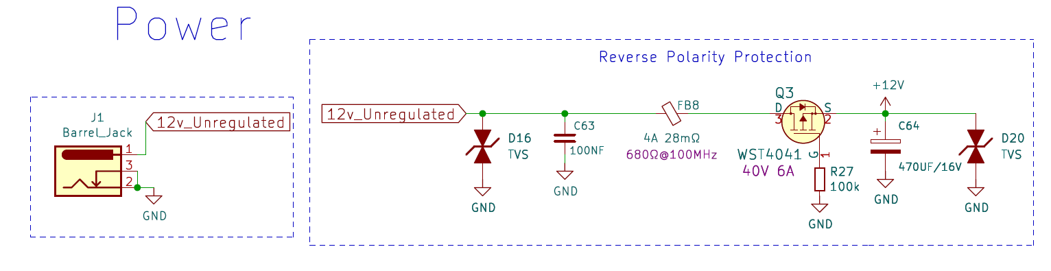
A “wall-wart” supplies +12v to the SJ-201 via Barrel Jack J1. This input passes to a reverse polarity protection circuit providing transient/overvoltage prevention and ensuring that a “backwards” power connection cannot damage the unit. This is certainly a conservative design: I’d expect the wall-wart supplied with the Mycroft II to be reasonably clean and regulated, and center-positive power connections are the norm. In a DIY power circuit I’d likely leave these components out. The pass transistor WST4041 caught my attention as a possible fail point for killing the SJ-201.
After passing through the polarity protection, the +12v is used to power theTI Audio Amplifier circuit TAS5806MD and is also passed to voltage regulator XL4501E1 which produces a +5v output. In turn, the +5v output is passed to an LDO (Low Drop Out) regulator AM1117-3.3 to produce +3.3v and to Buck Convertor MP2359 to produce a +1.0v output. The MP2359 includes an enable signal to control its output.
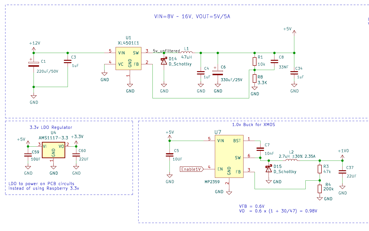
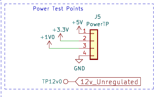
Looking ahead to troubleshooting, the circuit review shows that a failure of the +12v domain will result in all SJ-201 power supplies failing. If the +12v domain is healthy, then inspection of the +5, +3.3, and +1.0 volt derived domains might identify a fail mechanism. Test points are provided on the SJ-201 for easy voltmeter access.
Initial Mycroft II / SJ-201 Inspection:
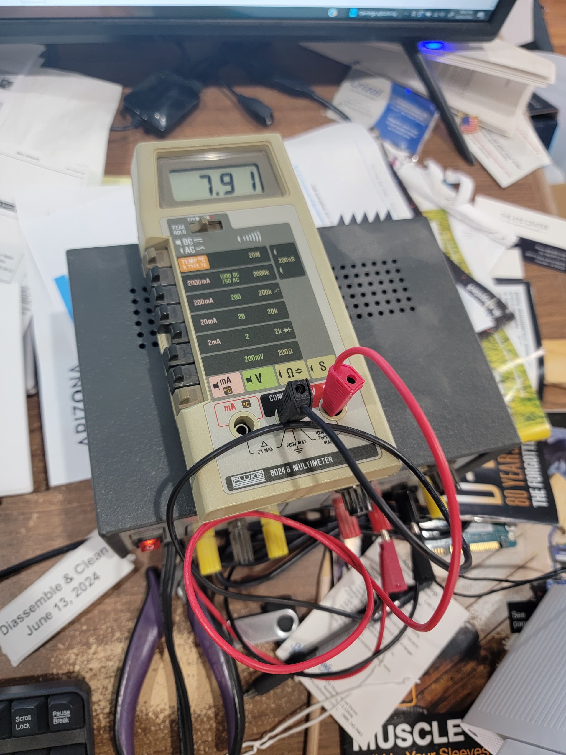
The first unit analyzed had identification 10000 004e96 88e2. Clary had provided this defective unit with a new wall-wart supply. I first tested the wall-wart with my multimeter and obtained 12.26 volts. I used this wall-wart to power up a known good Mycroft II successfully, confirming proper operation of the wall-wart. I then used the wall-wart to attempt a power-up of the defective unit – nothing, as expected.
https://blog.graywind.org/posts/mark2-teardown/
I disassembled the defective Mycroft following Mike Grey’s procedure and removed the SJ-201 to my bench top. My first hypothesis to test was a possible fail open of WST4041, the pass transistor in the Reverse Polarity Protection Circuit. I plugged the wall-wart into the SJ-201 and measured the voltage on the output pins of Barrel Jack J1. To my surprise, the reading was approximate 0.5v, indicating a pretty solid short somewhere. If the +12v input to the board was shorted, none of the other power supplies would be expected to function and the totally dead behavior of the Mycroft made sense. For completeness I measured the test points for the +5, +3.3, and +1.0 volt domains and obtained readings of zero, as expected.
At this point, a pass transistor fail could be ruled out: An open circuit between and of the transistor leads would not affect the wall-wart voltage. If the source to drain connection in the transistor were shorted, the +12v supply would simply pass “downstream” and all power domains would remain functional. What about a source-gate or drain-gate short? Inspection of the schematic shows the gate is connected to circuit ground through a 100k ohm resistor. So a gate short with +12v input could only pass 120 micro-amperes to ground. This would have no effect on the wall-wart having a three ampere output capability.
What about the transient suppressors D16, D20, and any capacitors connected to the +12v domain throughout the board? Any of these could be a fail location, but I initially looked elsewhere: I hoped that the transient suppressors would be reasonably reliable, since their design/purpose is to mitigate voltage excursions. Capacitors could fail, but one principle of circuit troubleshooting is to suspect active (i.e. transistor, semiconductor) devices ahead of passive (resistor, capacitor, inductor) components. With this in mind, I turned my attention to the XL4501E1 voltage regulator. If this device had developed a short to ground, it could potentially kill the +12v power domain. I unsoldered the input lead (#5) on the device and re-tested the +12v supply at the barrel jack: still shorted. Disconnection of the input to the XL4501E1 effectively removed the +3.3v and +1.0v supplies from the circuit, giving evidence that these were not contributing to the observed failure.
There is one more active device attached to the +12v power domain – the TAS5806MD audio amplifier. This device is manufactured by Texas Instruments. In my experience TI components have excellent reliability. It would be distressing if the amplifier circuits were responsible for the rash of SJ-201 fails. Given the complexity of removing or testing the TAS5806MD, I elected to assume the amplifiers were not suspect at this time.
This brings our attention back to the capacitors and transient voltage suppressors. In-circuit testing of components is difficult at best, and often impossible. In most cases it becomes necessary to disconnect one lead of a component to isolate it for testing. I lacked the equipment (and patience) needed for this approach. Although my personal test resources are limited I do have a thermal imaging camera attachment for my smartphone. Thermal imaging can often identify defective components by detecting the heat produced by a short circuit.
I used my thermal camera to image the SJ-201 when connected to the wall-wart. The image showed two obvious hot spots: one was associated with theWST4041 pass transistor. This is reasonable, since the transistor is being required to carry the excess current drawn by the short. A second hot spot was observed in the vicinity of the audio amplifier. Examination of the SJ-201 showed capacitors C13 and C14 in this area. The schematic shows that these capacitors are attached to the +12v power supply, presumably to provide decoupling (noise reduction) to the current supplied to the audio amplifier. A short in one of these capacitors could be responsible for killing the +12v supply and producing the observed hot spot. My thermal camera is a first-generation device with comparatively low resolution (206x156) so I had to guess which capacitor was emitting the heat. The small size of the device and thermal coupling into the circuit board made a touch test inconclusive. I made an overlay of the thermal image with a visual photograph of SJ-201. My best guess was to suspect capacitor C13.
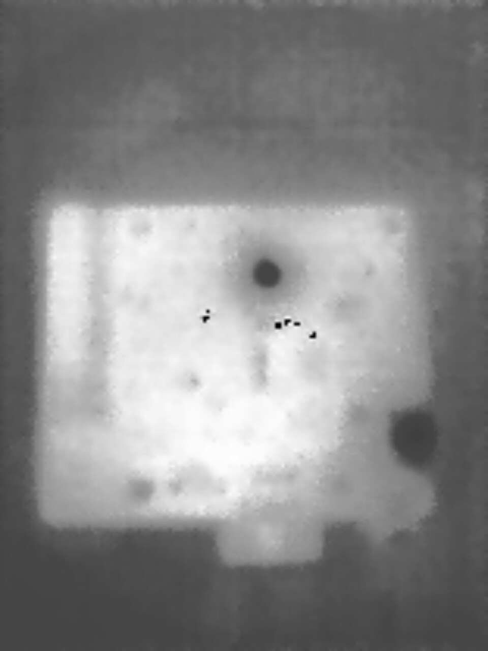
Thermal Image of SJ-201 with shorted +12v supply.
(The small dark pixels are defects in the thermal imager - ignore.)
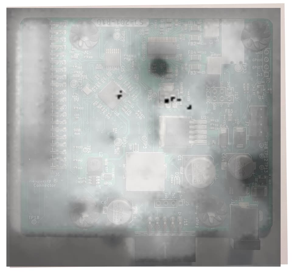
Thermal image overlay on SJ-201 PCB image. Note hot spots at pass transistor on right side and just below the audio amplifier near top center.
I unplugged and used a heat gun and tweezers to C13 from the circuit board. I then plugged the wall-wart back in and performed a voltage check: At the barrel jack I measured 12.26v. At the power test points I measured 5v, 3.3v and 0v. The 1v supply output was off, but this made sense since the SJ-201 was isolated from the Pi and had no enable signal. Good enough.
I reassembled the Mycroft II and was able to successfully boot the unit up OS 24.4.8. (I placed this unit into service May 14, 2024 and it has remained functional since that time.)
After my remedial action restored the SJ-201 to functionality I did some additional investigation into the failure, examining the SJ-201 schematics and BOM: Capacitors C13, C14, C19, and C20 are listed as manufacturer’s part number CL10A226MQ8NRNE. This is a Samsung capacitor, 22uf, rated for 6.3v operation. However, these capacitors are being used for decoupling a +12v supply to the TI amp, so they are being subjected to overstress. BTW, I was looking at the R10 (production) revision schematics, which matches the silkscreen number on the board I analyzed.
Failure Confirmation:
Although I was successful restoring operation to one SJ-201, was the failure identified unique, or is the mechanism responsible for the rash of dead Mycroft II units?
Clary was kind enough to supply me with three additional dead Mycroft II devices. If I understood her communication correctly, these units had not been analyzed to confirm dead SJ-201 boards; they were simply known to not work.
Starting with the hypothesis of a failed decoupling capacitor (C13, C14, C19, C20) I followed an abbreviated analysis procedure:
*) Plug in 12v wall-wart and confirm presence of a short with voltage measurement at barrel jack
*) Image using thermal camera with identification of a hot spot at a decoupling capacitor
*) Pry offending capacitor off the PCB
The same failure mode was observed in each of the three additional Mycroft II units. Additionally, I was able to restore operation in each unit by removal of the offending capacitor.
Unit ID Capacitor Removed
100000 00f7fd 6ce0 C20
100000 0043a0 d99b C20
100000 003578 c476 C14
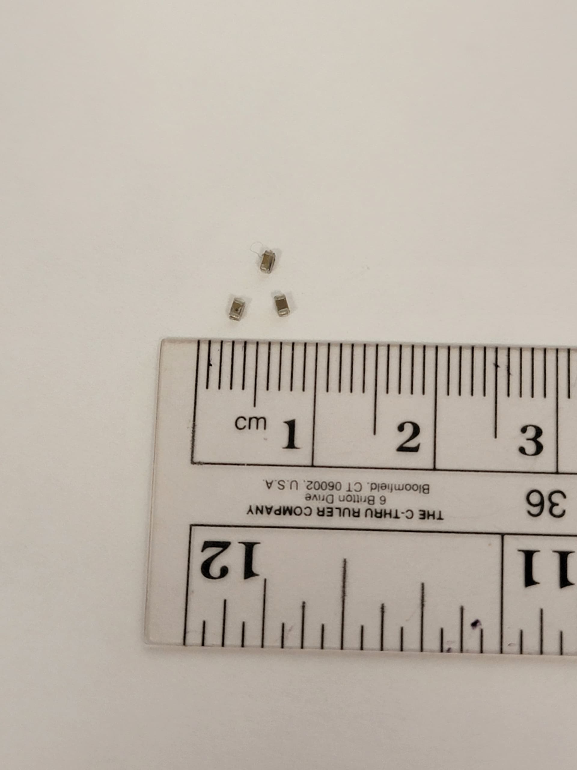
Offending Capacitors Removed from SJ-201 Boards
I also confirmed voltage at the 5v and 3.3v test points after capacitor removal; as mentioned earlier the 1v test point remained at zero since the enable signal was not available at the voltage regulator.

Mycroft II Units Operating After SJ-201 Service
Miscellaneous Notes and Observations:
*) All units in this analysis had R10 revision SJ-201 boards
https://github.com/MycroftAI/hardware-mycroft-mark-II/tree/master/mark-II-production
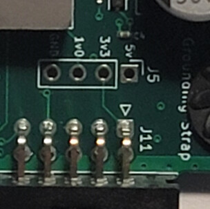
*) To access the SJ-201, it is not necessary to completely disassemble the Mycroft. Instead you can:
- open the front
- disconnect the ribbon cable to the display
- unplug the speaker connections
- unplug the fan connection
- remove three screws securing the Pi/SJ-201 module in place
- carefully slide out leaving the camera cable connected to the Pi
- unplug the Pi from the SJ-201 leaving the SJ-201 attached to the top plate
*) Any one of the four capacitors listed could be a fail point. Although removal of a shorted capacitor may restore the operation of the SJ-201, the remaining capacitors on the board could fail in the future.
*) Without a thermal camera, identification of the specific failing capacitor will be difficult for the DIY user. A person with sensitive touch (not me) may be able to detect a warm device, or perhaps one could chill the board and breathe on it to fog the surface? Persons who enjoy gambling could pull the capacitors off one at a time, but…
*) Removal of all four capacitors might prevent board failure by shorting, but the operation of the audio amplifier may be compromised without power supply decoupling. I did not want to perform this experiment because it risked ruining an otherwise useful Mycroft device.
*) Instead of unsoldering the defective capacitor from the SJ-201, I was able to simply pry the devices off using a hemostat tool. Just be gentle!
*) Be careful with the ribbon connections to the Pi; they are kinda delicate.
Conclusions:
The decoupling capacitors C13, C14, C19, C20 are likely the root cause of most SJ-201 fails being reported. I’m very frightened. I assume virtually all Mycroft II units have a ticking time bomb inside. If I encounter future SJ-201 failures in my Mycroft II units I intend to repeat the analysis and remove additional capacitors as necessary.
Disclaimer:
I am simply summarizing the investigations I performed and actions I took. I am not recommending that anyone attempt to duplicate my efforts. YMMV and you may experience disaster.
I am terming the actions I performed as a “remedy” for the failure, and not a repair. By removing the decoupling capacitors the performance of the audio amplifier may be compromised. Furthermore you may be negating device compliance regulations (e.g. CE, FCC) in your region. If you go prison for 100 years I am not going to visit you.
A proper repair would consist of removing the problematic capacitors and replacing them with devices having a higher (>12v) voltage rating. This requires equipment for surface mount soldering/desoldering that is unlikely to be found with the average DIY hobby enthusiast. Having a commercial repair facility perform the replacement would not likely be cost effective.